


New Mexico Geochronology Research Laboratory
Hardware — CO2 Laser
Note: The description below is out of date and will be revised soon.
The CO2 laser system used by the NMGRL consists of...
- Advantages of a CO2 laser system
- Inexpensive to purchase, operate and maintain
- excellent beam coupling to silicate minerals
- rapid sample heating relative to the resistance furnace
- very low argon background or blank levels relative to resistance furnace
- ideal for identifying sample heterogenities (e.g. non-desirable mineral phases, xenocrysts)
- capable of step-heating with special lenses
- Disadvantages of a CO2 laser system
- incapable of very small (<1 mm beam spot sizes, as is necessary for in-situ argon extraction (see UV laser)
- even with special lenses for step-heating, homogeneous heating difficult
Schematic of NGMRL CO2 laser system
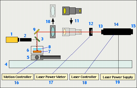
Components of the NMGRL CO2 laser system.
-
Color CCTV camera (Polnux TMC-574)
-
Optical lens
-
IR transparent optical mirror
-
Vibration isolated workstation/table (Newport Corporation)
-
Automated stage:
-
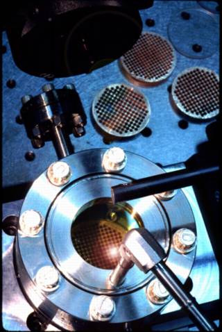
Sample chamber: base = 3.375" flange; window = ISI ZnSe 1.5 window mounted in 3.375" flange
-
Copper sample holder; 6 to 221 sample pits
-
Potassium bromide cover slip: 2mm thick x 38.1 mm diameter
-
first surface silicon mirror
-
1" diameter by 5" focal length ZnSe meniscus lens, II-VI #376587
-
Beam integrator lens
-
Laser power meter head; Molectron PM150-19-C, swings in or out of beam path to measure beam intensity
-
Laser feedback diode, Synrad CA-48-CL
-
50-watt CO2 laser, Synrad 48-1-28W
-
He-Ne pointer laser, Synrad He-Ne
-
Two-axis motion controller with IEEE.488 communications, Newport PMC200-P
-
Laser power meter, Powermax 5100
-
CO2 laser controller with 0-10 volt DC input, Synrad UC-1000
-
0-40 volt, 10 amp power supply with 0-10 volt input, Lambda LLS8040